Verification is a complex process. It consumes about 80% of the time and effort that goes into a typical ASIC cycle. With the rise in complexity of designs and an ever-rising demand for smarter electronics, the pressure on the semiconductor industry to tapeout better designs within short intervals of time is mounting. In such a scenario, it is imperative to ‘reuse’ for both the design as well as verification engineers. While designers ‘reuse’ existing design IPs, verification engineers must deploy third-party VIP (Verification IP) in their test bench to accelerate the design verification process. Since the timelines to churn out ‘improved’ designs and hence verify them are too tight, it is necessary for the test bench development time to be small. Designs are also expected to behave differently when configurations are tweaked and obviously the test benches must follow suit. Hence, building ‘reusable’, ‘configurable’ and ‘scalable’ test benches and verification components have become more of a necessity than a fad.
SystemVerilog that borrows its concepts from VHDL, Verilog and OOPS (Object Oriented Programming System) is now the most widely adopted HVL (Hardware Verification Language). It raises the abstraction level of test benches several octaves higher, it also comes loaded with concepts and features that help build scalable, configurable and reusable test benches. But, in order to make the test benches plug and play a ‘common’ rule book must be followed by all VIP companies. This rule book in the verification context is called a ‘Verification Methodology’. A Verification Methodology enhances and simplifies the verification process by laying out a set of guidelines to follow while defining, configuring and interconnecting each and every component of the layered test bench architecture. It also comes with a Base Class Library (BCL) that serve as ‘building blocks’ to build complex, reusable and interoperable code with ease. Just as SystemVerilog rules the roost in the HVL arena, UVM (Universal Verification Methodology) is the cynosure of all eyes too. UVM is an Accellera standard that is backed by the big names in the EDA (Electronic Design Automation) industry such as Synopsys, Mentor, Cadence and Aldec. Thus, it not just helps in building ‘standardized’ test benches and makes them ‘interoperable’, but also makes the code simulator independent.
We shall discuss the UVM test bench architecture and the significance of each of its components at length in the sections to follow.
An Overview on Layered test bench Architecture
UVM focusses on two primary aspects, one is to cut down time and effort in developing verification code. The second and also a very vital purpose is to enhance code reusability. There are four key concepts in UVM: Reporting, Configuration Database, Factory and Simulation Execution Manager. Before we discuss these concepts, let us talk about a ‘basic layered test bench’ and its components.
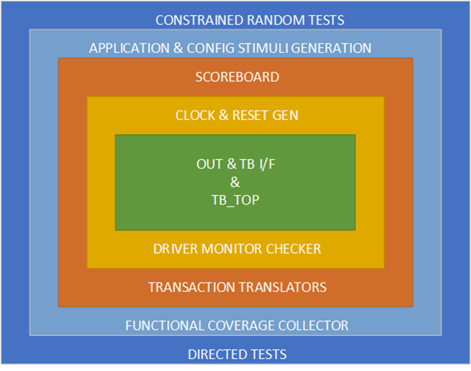
The layered test bench architecture refers to the grouping of test bench components into layers based on their functionality. A parallel with the OSI (Open System Interconnect) model can be drawn because like the OSI model, each layer of the layered test bench not just performs a set of unique functions, but also helps the higher layers in executing their functions. The layered test bench is essentially divided into five layers as described below.
- Layer 1 is the test bench top layer. The signal level connections between the DUT and verification environment happens here. This layer may also contain any ‘glue logic’ that is needed to make the signal level connections.
- Layer 2 is the layer of Bus Functional Model (BFM), BFMs are quintessential components of a test bench that convert transaction objects into signal level information.
- Layer 3 comprises of components that convert application level information exchange into BFM transactions. For e.g. retrieving a ‘’phone contact’ application is essentially a ‘memory read’ transaction.
- Layer 4 comprises of the stimulus generation logic, which includes both data and control related stimulus. The constraints on both data and control configurations are defined in this layer.
- Layer 5 comprises of the constrained random or directed test cases. Each test case is defined to test a set of features or a single feature. Every test case tweaks the stimulus generators and configuration logic to generate a unique scenario.
A Typical UVM test bench
A UVM test bench is based on the fundamentals of the layered test bench architecture. A UVM test bench comprises of ‘Static’ as well as ‘Dynamic’ components. The components that are destroyed at the end of simulation such as sequences and transactions are referred to as ‘Dynamic’ components, while the components that are ‘physical’ components and exist even after the simulation has ended are defined as ‘Static’ components. Drivers, Generators, Monitors, Scoreboards, etc are examples of ‘Static’ components. Let us take a quick look at each of the components of the UVM Environment in more detail.
- Top level: At the highest level is the ‘top module’ that instantiates ‘test case’, VE, DUT and all the other logic such as the clock and reset generation.
- test case: The test cases are directed or constrained random based on ‘how’ they are configured. A test case drives one or multiple sequences that are nothing but a bunch of transactions.
- Interface: An ‘interface’ encapsulates communication between the DUT and the VE.
- Clock and Reset Logic: This block contains logic to drive the reset sequence as well as clock the VE as well as DUT.
- Checkers: This module like the ‘monitor’ and ‘driver’, functions at the ‘signal level’. It comprises of a bunch of ‘assertions’. It keeps a continuous eye on the signals and serves to look for protocol violations and other signal level discrepancies.
- Verification Environment: This comprises of all the components that are required to verify a DUT (Device Under Test). The VE typically consists of transaction generator, driver, monitor, scoreboard, functional coverage collector and transaction object(s). Each component may also contain configuration settings.
- Sequence_item: A sequence item is a dynamic component of the VE, it can be defined as a bunch of transactions. A bunch of write transactions to a set of ‘desired’ address space can be termed as a ‘sequence’.
- Transaction: A transaction is a set of variables, constraints and methods that operate on themselves. A memory write transaction object would typically contain a memory ‘address’ and ‘data’ to be written and corresponding constraints.
- Agent: An agent also refers to something that performs an active role and produces a desired output/effect/response. The ‘agent’ module comprises of ‘monitor’, ‘driver’, ‘functional coverage collector’, ‘sequencer’ and the configuration settings for each of these sub-components and the agent in its entirety. The ‘sequencer’ generates transaction sequences and transfers those sequences to the driver via a ‘TLM’ (Transaction Level Modeling)interface. The ‘driver’ contains logic to map ‘transactions’ into corresponding ‘signals’ level transitions. The ‘monitor’ as the name suggests ‘monitors’’ these signal level transitions to scan and report signal level issues. The ‘monitor’ module communicates with the DUT via a signal level interface. It passes the transaction object received from the DUT output to the scoreboard via a TLM. The ‘functional coverage collector’ module receives its input from the sequencer and/or driver and thus knows the ‘nature of stimulus’ provided to the DUT. It possesses the intelligence to assess if all the possible stimuli have been exercised upon the DUT.
- Scoreboard: The ‘scoreboard’ communicates with the monitor module via a TLM. It also receives input from the sequencer. Thus, scoreboard essentially knows what stimulus was injected into the DUT and what was received. It then verifies if the DUT output corresponds to the input.
- Virtual Sequencer: A virtual sequencer is a component that produces top-level sequence or in other words ‘application’ level stimuli. It is not a part of an agent as the sequences generated by a ‘virtual sequencer’ are high level and virtual sequencers do not communicate directly with drivers. Let us take an example of a design that has more than one port, it could be a network switch. There would be multiple agents corresponding to the number of switch ports. But a single virtual sequencer sits on top of the multiple agents to schedule/manage/synchronize the sequences to be driven based on the scenario defined in the test case layer.
- Test case Layer: The scenario definition happens at this level. A simple example of a scenario is verifying the reset response of the design or checking if the data written to memory space is read back correctly. A test case tweaks an array of configurations/constraints and often they need to be ‘setup’ to verify a scenario. Hence the test layer also have the configuration controls embedded.
What makes UVM so popular?
Reporting mechanism in UVM: The reporting and messaging mechanism in UVM contains a bunch of methods and command line options that help in changing the amount and type of messages displayed during the simulation. One need not recompile the design. By means of UVM Reporting Object, it becomes possible to control the ‘Severity’, ‘Verbosity’ and ‘Simulation Handling’.
Config Database: Is a ‘centralized’ database that can be used to store as well as retrieve different ‘types’ of information. The data stored in the database can range from queues, class handles or even virtual interfaces. The config_db works like a repository wherein ‘certain’ portions of the test bench can be stored and can also be pulled out to build a different framework. Thus, making modifications in the test bench or even parameterizing it can be simplified with the use of config_db
Factory: UVM factory can be viewed as a LUT (Look Up Table) wherein all the components and their extensions/derivatives need to be registered when defining them. It is not recommended to allocate memory to UVM test bench components by invoking the new() method. Instead, the test bench components must be ‘created’ and ‘registered’ into the ‘UVM Factory’. The greatest advantage that UVM Factory offers is that it facilitates the substitution of a base class object with a derived class object without having to modify test bench code. UVM Factory allows both ‘Type’ and ‘Instance’ based overriding.
Simulation Execution Manager: Simulation execution is primarily divided into three main phases, i.e., ‘Build’ phase, ‘Run’ phase and the ‘Cleanup’ phase. The static components of the VE are built, configured and interconnected in the ‘Build’ phase. The stimulus is applied to the DUT in the ‘Run’ phase and this is the only phase that takes time to execute. While the cleanup phase involves freeing up memory allocated to the dynamic components and the test results are collected and reported. The edge that UVM offers is that each of these phases is divided into multiple sub-phases. Thus enabling finer control over the simulation.
Summary
Verification has gone through a sea change after the introduction of HVLs and Verification Methodologies. SystemVerilog is the most widely adopted HVL for it comes loaded with features that have played a pivotal role in building ‘smarter’ test benches. Verification Methodologies such as AVM, UVM, RVM, OVM, VMM and the likes chipped in to fill the hole that HVLs could not fill. They brought in a ‘rule book’ and a set of BCL (Base Class Library) that helped build interoperable and reusable test bench components. This made ‘reuse’ of third-party VIPs possible.
UVM stands for Universal Verification Methodology, is now the most widely adopted Verification Methodology. The UVM test bench components are structured in a layered fashion. There are mainly two types of components in a typical UVM test bench; Static & Dynamic. The ‘agent’ module comprising of ‘Driver’, ‘Monitor’, ‘Sequencer’ and ‘Functional Coverage Collector’ and other components such as ‘Scoreboard’ and ‘Checker’ can be classified as ‘Static’ components of the test bench. While the sequences and/or transactions that are driven can be viewed as ‘Dynamic’ elements of a UVM test bench. The test bench communicates with the DUT via an ‘Interface’, the driver and monitor communicate with the design at a signal level, while the sequencer to driver and scoreboard to monitor communications happens at the ‘transaction’ level. UVM brings in an array of upgrades in the way test bench building happens and they include an improved ‘Reporting and Messaging’ mechanism, ‘Config Database’ that serves as a ‘centralized’ database for storing as well retrieving information. The ‘factory’ feature of UVM makes a substitution of a base class object with a derived class object simpler while the Simulation Manager divides each simulation phase into multiple sub-phases in order to render ‘finer’ run-time control. UVM is an Accellera standard backed by all major EDA companies in the industry, thus UVM based test benches are not just interoperable and reusable, they are simulator independent too! No wonder, UVM is found almost everywhere in the semiconductor arena.